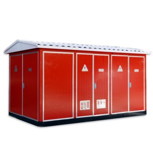
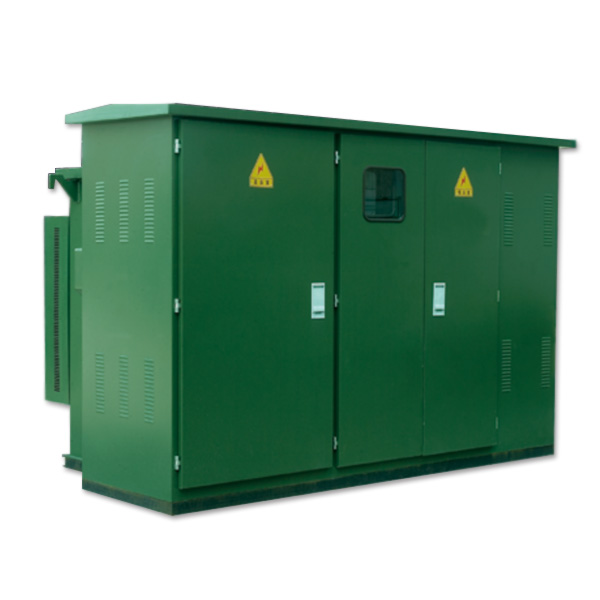
ZGS13-H American prefabricated box-type substation
Overview
This product is developed by absorbing the latest advanced technology from abroad and combining with the actual situation in China. The whole product has the characteristics of small size, easy installation and maintenance, low noise, low loss, anti-theft, strong overload capacity, and full protection. It is suitable for new residential areas, green belts, parks, station hotels, construction sites, airports and other places.
ZGS13-H series American prefabricated box-type substation is suitable for 10kV ring network power supply, dual power supply or terminal power supply system, as transformer, metering, compensation control and protection device.
This product meets the following standards: GB / T17467-1998 “High-voltage low-voltage prefabricated substation”, DL / T537-93 “Technical conditions for ordering 6-35kV box-type substation”
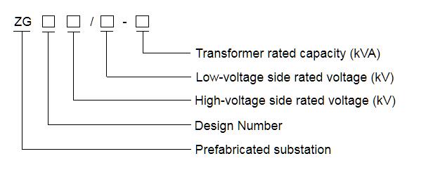
Model Meaning
Functions and Features
♦ Fully insulated, fully sealed, free of maintenance, and reliable to ensure personal safety;
♦ Compact structure, the volume is only 1/3-1/5 of the same capacity European variable, and the height is low;
♦ The sub-box structure can be used to avoid oil pollution in the transformer tank;
♦ Double-fuse full range protection is used on the high-voltage side, which greatly reduces the cost:
♦ Both ring network and terminal can be used. The cable head can be plugged in and out at 200A load current;
♦ The box adopts honeycomb double sandwich composite board, which has the function of temperature insulation and heat dissipation;
♦ An electronic phase loss protector is installed on the low-voltage side. When an abnormal voltage occurs in the system, the main inlet switch can be quickly disconnected;
♦ High-pressure side oil-immersed load switch or SF6 load switch can be electrically upgraded to lay the foundation for the automation of distribution network.
♦ Use oil-immersed S9 or S11 series transformer with better performance.
Normal operating conditions
♦ Altitude not exceeding 1000 m
♦ Ambient temperature :-35°C 〜+40°C
♦ Relative humidity: daily average is not greater than 95%, monthly average is not greater than 90%;
♦ Installation place: no fire, explosion hazard, chemical corrosive gas and well ventilated place, the ground inclination angle is not more than 3°.
Technical parameters of load switch
Prefabricated substation technical parameter table
| Serial number 1 | Name | Unit | Technical parameters |
| 1 | Rated voltage | kV | 10/0.4(high/low) |
| 2 | Maximum operating voltage | kV | 12(high voltage side) |
| 3 | Rated frequency | Hz | 50 |
| 4 | Rated capacity | kVA | 50-1600 |
| 5 | 1 minute power frequency voltage | kV | 35 |
| 6 | Lightning impulse voltage | kV | 75 |
| 7 | Cooling mode | Oil immersed self-coolilng | |
| 8 | High voltage back-up fuse breaking current | kA | 50 |
| 9 | Plug-in fuse breaking current | kA | 2.5 |
| 10 | Ambient temperature | -35-+40 | |
| 11 | Coil allowed temperature rise | k | 65 |
| 12 | Non-load voltage regulation | ±5% or ±2 x2.5% | |
| 13 | Noise level | dB | 50 |
| 14 | Protection level | IP43 | |
Transformer Technical Parameters
The new S9 series transformer body is selected, with low loss, good overload capacity, and strong short-circuit resistance. All fasteners are treated with anti-loosening treatment and no core is required; S10 series and S11 series transformers with better performance can also be used.
| CapacitykVA | Voltage kV | Join group label | No-load current% | No-load current% | Impedance voltage% | S9 | S10 | S11 | |||||
| High voltage | Low voltage | S9 | S10 | S11 | S9 | S9 | S11 | ||||||
| 50 | 2.0 | 1.9 | 0.75 | 0.17 | 0.15 | 0.12 | 0.87 | 0.83 | 0.87 | ||||
| 63 | 1.9 | 1.8 | 0.7 | 0.2 | 0.18 | 0.14 | 1.04 | 0.99 | 1.04 | ||||
| 80 | 1.9 | 1.7 | 0.7 | 0.25 | 0.22 | 0.175 | 1.25 | 1.2 | 1.25 | ||||
| 100 | 1.8 | 1.55 | 0.65 | 0.29 | 0.26 | 0.2 | 1.5 | 1.42 | 1.5 | ||||
| 125 | 1.7 | 1.45 | 0.65 | 0.34 | 0.3 | 0.235 | 4.0 | 1.8 | 1.72 | 1.8 | |||
| 160 | 1.6 | 1.3 | 0.6 | 0.4 | 0.36 | 0.27 | 2.2 | 2.12 | 2.2 | ||||
| 200 | 10+5% | Dyn11 | 1.5 | 1.2 | 0.55 | 0.48 | 0.43 | 0.33 | 2.6 | 2.5 | 2.6 | ||
| 250 | or | 0.4 | or | 1.4 | 1.1 | 0.5 | 0.56 | 0.5 | 0.39 | 3.05 | 2.9 | 3.05 | |
| 315 | ±2 x 2.5% | Yyn0 | 1.4 | 1.0 | 0.45 | 0.67 | 0.29 | 0.465 | 3.65 | 3.45 | 3.65 | ||
| 400 | 1.3 | 1.0 | 0.4 | 0.8 | 0.71 | 0.56 | 4.3 | 4.15 | 4.3 | ||||
| 500 | 1.2 | 1.0 | 0.4 | 0.96 | 0.85 | 0.67 | 5.15 | 4.82 | 5.15 | ||||
| 630 | 1.1 | 0.8 | 0.4 | 1.2 | 1.6 | 0.81 | 6.2 | 5.86 | 6.2 | ||||
| 800 | 1.0 | 0.7 | 0.35 | 1.4 | 1.23 | 0.98 | 7.5 | 7.2 | 7.5 | ||||
| 1000 | 1.0 | 0.6 | 0.3 | 1.7 | 1.5 | 1.15 | 4.5 | 10.3 | 9.8 | 10.3 | |||
| 1250 | 0.9 | 0.6 | 0.27 | 1.95 | 1.72 | 1.36 | 12.0 | 12.2 | 12.0 | ||||
Technical parameters of load switch
The load switch is oil-immersed, three-phase linkage switch, spring operating mechanism; it can be opened and closed with load, its opening and closing speed has nothing to do with the size of the operating force, the type has two stations, four stations D type, four stations V Types are available.
Main technical parameters
|
Serial number |
Name |
Unit |
Four station ring network load switch |
Two station load switches |
|
|
1 |
Rated current |
A |
630 |
315 |
|
|
2 |
Rated short-circuit closing current |
kA |
31.5 |
31.5 |
|
|
3 |
Rated short-time withstand current |
kA |
12.5 |
12.5 |
|
|
4 |
Rated short time withstand time |
s |
2 |
2 |
|
|
5 |
Mechanical life |
times |
2000 |
2000 |
|
|
6 |
Lightning impulse withstand |
Interphase to ground |
kV |
75 |
75 |
|
7 |
Voltage peak full wave |
Isolation fracture |
kV |
85 |
85 |
|
8 |
1 min Power frequency withstand voltage |
Interphase to ground |
kV |
42 |
42 |
|
9 |
Isolation fracture |
kV |
48 |
48 |
|
|
10 |
Rated peak withstand current current |
kA |
31.5 |
31.5 |
|
Technical parameters of fuses (recommended table for selection of oil-immersed fuses)
The high-voltage side of the American box substation is protected in series by a backup protection fuse and a plug-in fuse. The principle is simple, economical and reliable; the backup protection fuse is an oil-immersed high-voltage current-limiting fuse with a large breaking capacity, only inside the transformer Action in the event of a fault, a double-sensitive fuse is installed in the plug-in fuse, which can provide dual protection of current and temperature. After the double-sensitive fuse is blown, the fuse can be easily replaced on site.
| Serial number |
Capacity of three phase transformer (kVA) |
Transformer primary voltage (10 kV) |
|
|
XRNT rated current (A) |
PRNT1 overload protection rated current (A) |
||
| 1 |
30 |
10 |
6 |
| 2 |
50 |
16 |
8 |
| 3 |
80 |
16 |
10 |
| 4 |
100 |
20 |
15 |
| 5 |
125 |
25 |
15 |
| 6 |
160 |
31.5 |
25 |
| 7 |
200 |
40 | 25 |
| 8 |
250 |
50 | 40 |
| 9 |
315 |
63 | 40 |
| 10 |
400 |
63 | 40 |
| 11 |
500 |
80 | 50 |
| 12 |
630 |
100 |
50.65 |
| 13 |
800 |
125 | 65 |
| 14 |
1250 |
160 |
100 |
| 15 |
1600 |
200 |
140 |
Box substation Structure
The product box structure is composed of three parts: high-pressure interval, low-pressure interval and oil tank interval. The high-voltage compartment includes high-voltage cable accessories, load switches, no-load voltage-regulating tap-changers, plug-in fuses, pressure relief valves, oil level gauges, oil temperature gauges, and oil drain valves. The low voltage interval includes low voltage bushing, low voltage meter, circuit breaker, and capacitance compensation. The oil tank compartment includes transformer winding and iron core, radiator, high-voltage load switch and fuse are all in the oil tank. According to the requirements of the plan, the tank variable structure can be designed into “product” font or “mesh” font.
Figure 1: Structure diagram of prefabricated substation
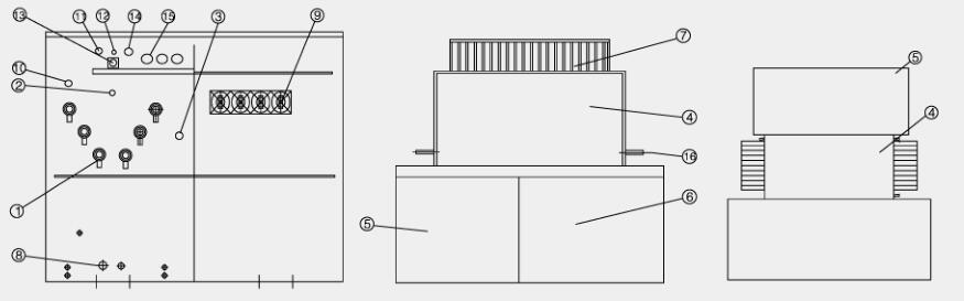
| 1.High voltage insulated sleeve | 5.High voltage chamber | 9. low voltage sleeve |
13.Oil level gauge |
|||
| 2.Load switch | 6.Low voltage chamber | 10. Oil thermometer |
14.Oil injection holes |
|||
| 3.Tap-changer | 7.Radiator | 11. Pressure gauges |
15.Plug-in fuses |
|||
| 4.Transformer | 8.Drain valve | 12. Pressure relief valves |
16.Hook |
|||
Operating instructions
Operation of load switch:
There are three types of oil-immersed load switches used in American box transformers: two-station, four-station T-type, and four-station V-type.
The three operations are as follows:
The four-station V-type load switch is shown in Figure 2. The structure of the power piece is a “v” type structure. The black part in the figure is shown.
Prepare a fuse, insert the fuse and connect the transformer high voltage incoming line. Ring network load switch with load to switch the network.
The four working states of the load switch:
1. In the “Ⅰ-Ⅱ -T” position, the “Ⅰ” and “Ⅱ” two networks are connected, and the transformer has electricity;
2. At the “I -T” position, the “I” network is connected to the transformer; (starting and ending of the substation)
3. At the “Ⅱ -T” position, the “Ⅱ” network is connected to the transformer; (starting and ending of the substation)
4. In the “O” position, the “Ⅰ, Ⅱ” network and the transformer are disconnected; (all without electricity)
Insert a special operating handle into the load switch shaft and rotate it about 130 ° clockwise or counterclockwise. Each time the load switch is operated, the power strip rotates by one gear. Example of switch operation: Change from “I” power supply to “II” power supply.
a. Insert the special operation handle into the switch shaft;
b. Turn the switch clockwise once, at this time the switch “V” blade is in the “I-II -T” position;
c. Turn it again in the clockwise direction. At this time, the “V” blade is between “II-T” to supply power to the power supply “II”; the operation is completed.
Operation 2:
a. Insert the special operation handle into the switch shaft;
b. Turn the switch counterclockwise once, at this time the “V” blade is in the “O” position:
c. Turn it again in the counterclockwise direction, at this time, the “V” blade is between “II-T” to supply power to the power supply “II”; the operation is completed.
The above two methods can be used to complete the conversion from power supply “I” to power supply “II”, but the second method is safer and more reasonable. After the power supply “I” is cut off, it will not be sent again, and if the power supply “II” fails, it will not cause a closure. With the first method, dual power supply will appear. When the power supply “I” is converted to the power supply “II”, if the power supply phase is different, the fault will be caused.
Four-station ring network load switch (T type) The working principle of the four-station “T” type load switch is shown in Figure 3, and the principle operation is the same as the “V” type.
Two station terminal load switch
The structure diagram is shown in Figure 4. “I” in the figure is connected to the high-voltage incoming terminal. During operation, the user inserts the special operation handle into the load switch shaft, and turns “90 °” in the counterclockwise direction. The load switch turns to the “open” gate position. The terminal load switch only uses the terminal power supply mode to cut off the transformer branch, or It works when replacing the core of the plug-in fuse, so the terminal load switch is only divided into two positions, and because of its small size, the operating force is also small, and the operation is very convenient. In order to reduce the oil pollution in the oil tank, it is recommended that the user turn off the low-voltage main switch or outlet switch before operating the load switch to cut off the low-pressure side load.
Cable head
a. The high-voltage inlet and outlet lines of the 12kV prefabricated substation adopt cable inlet and outlet lines, and the high-voltage power supply is led to the outside of the oil tank by an epoxy cast insulating sleeve. The ability to withstand voltage and lightning impulse withstand voltage.
b. Select the elbow or T-shaped cable head that matches the cable cross section, clean the inner and outer surfaces and the surface of the insulating sleeve with absolute ethanol, apply a little 7501 vacuum silicone grease on the surface of the sleeve, and follow the cable work area The special installation specification for the installation. For the installation of the cable head, please refer to the random manual.
Replacement of plug-in fuses
The plug-in fuse is an element that can replace the flame core externally. When replacing, first pull the button of the upper tank pressure release valve to balance the pressure inside and outside the tank. In order to ensure the safety of the operator and the equipment, the plug-in fuse is plugged and unplugged when there is no load, so first cut off the low voltage switch to cut off all the load on the low voltage side, and then use the operating handle to switch the load switch to the power and transformer disconnection position , And then use the operating handle to loosen the handle on the fuse holder, and then rotate it about 90 degrees to eliminate the adhesion between the gasket and the outer wall, and pull the fuse melt 70-80mm diagonally upward, stay Seconds, after the oil on the melt has drained off, pull out the melt to prevent the oil from dripping on other components outside the tank; wipe the surface of the melt with a clean cotton cloth and replace the core. When replacing, please pay attention to the parameters marked on the fuse core. Different parameters cannot be substituted. The replacement procedure is shown in the figure. After replacing the melt core, insert the melt into the fuse holder firmly. When the handle on the melt is turned to the locked position, make sure that the washer is close to the fuse holder and the handle is buckled on the boss Ensure that the substation is fully sealed and does not get wet. Then re-close the high-voltage load switch and low-voltage switch, and the power supply can be restored at this time.
Because the substation is a three-phase system, whether it is a backup protection fuse or a plug-in fuse, when one-phase melt blows, the general three-phase melt should be replaced unless it can be determined that only one phase melt has passed the fault current.
Replacement steps for plug-in fuses
1. The low voltage main switch opens;
2. High-voltage load switch opens;
3. Pull the pressure release valve ring to release the pressure:
4. Hook the operation hole and rotate upward 90 degrees;
5. 100mm upward, stop for a while, then pull out all;
6. Wipe dry with a clean cotton cloth;
7. Replace the fuse as shown below:
8. Quickly insert the replaced fuse core into the original hole and fasten it.
Handle Seal ring Fuse handle Fuse block End bolt
Transport、installation and maintenance
Transport
The substation leaving the factory should be filled with 25 # (or 45 #) transformer oil according to the oil level indicator in the oil tank. During transportation and loading and unloading, it is not allowed to be turned upside down and overturned, and it is not allowed to hit parts or shake strongly.
Special attention should be paid when the substation is lifted and shifted. The lifting hook should be hooked on the hook of the oil tank. The lifting should be done slowly to avoid the wire rope from damaging the surface of the substation and even causing the center of gravity of the entire substation to shift, tilt and fall.
Installation
♦ When installing the substation on site, pay attention to the protection of the paint on the surface of the cabinet. It is not allowed to collide and crack the handles of the barometer, oil level gauge, thermometer, plug-in fuse, and the insulating sleeve.
♦ Remove dust and dirt from the outside of the substation, inside the cabinet door, and the surface of the insulating sleeve.
♦ Check whether the nameplate data and product certificate of the substation are consistent with the purchase order, and check whether the documents and spare parts are missing according to the packing list.
♦ The civil engineering drawing of the cable entrance and exit line of the substation is shown in the figure.
Maintain
♦ The factory-made products have undergone strict assembly adjustments and do not need to be disassembled during installation to avoid affecting performance. Maintenance is limited to the following situations:
♦ Conduct sampling analysis of transformer oil once a year;
♦ If the oil level is found to be lower, it should be replenished in time. The oil grade is the same as the oil in the tank:
♦ After the fuse is blown, the reason should be found out. When replacing the fuse core, it should be noted that the specifications and models should be the same as the original specifications.
Experiments before acceptance and commissioning
♦ After unpacking, check whether the files and attachments are complete;
♦ Whether the oil level indicated by the oil level gauge meets the product regulations; whether the tap-changer is in the correct position;
♦ Carry out clockwise and counterclockwise operations on the load switch, four times each, and there should be no abnormal phenomena such as “refusal to divide and refuse to close”
♦ Measurement of DC resistance at high and low voltage side;
♦ Measurement of transformer ratio;
♦ Insulation resistance measurement and power frequency withstand voltage test (according to 80% at the factory).
Factory information
♦ The manufacturer should provide the following documents and accessories when supplying
♦ Shipping list
♦ Product qualification certificate and factory test report
♦ Instruction manual
♦ Related electrical drawings
♦ Description of main components
♦ Cabinet key, operating handle and spare parts specified in the contract.
Order Notes
♦ The following information must be provided to our company when ordering:
♦ Product model and quantity;
♦ Transformer model and capacity:
♦ Transformer oil (25 #, 45 #, high ignition point oil);
♦ High-low voltage side primary wiring scheme and main component parameters;
♦ Cross section of high-voltage incoming cable;
♦ Required spare parts.
Civil drawing of substation cable feed line (ZGS13-H) Technical requirements:
♦ For the size, please refer to the combination of actual size:
♦ The concrete platform should be flat on the surface, and the combined substation should be fixed on the platform with a pressure plate; the type of grounding bar and cable fixing bracket can be determined according to the actual situation;
♦ The cable fixing frame and grounding bar shall be pre-buried;
♦ The location of the cable hole of the inlet and outlet depends on the specific situation;
♦ After the combination transformer is installed, there must be a gap of not less than 1.5m on the front of the switch to facilitate operation; the grounding grid can be made of 12 galvanized round steel or 40×4 galvanized flat copper, and the grounding resistance should meet the requirements of the power department.
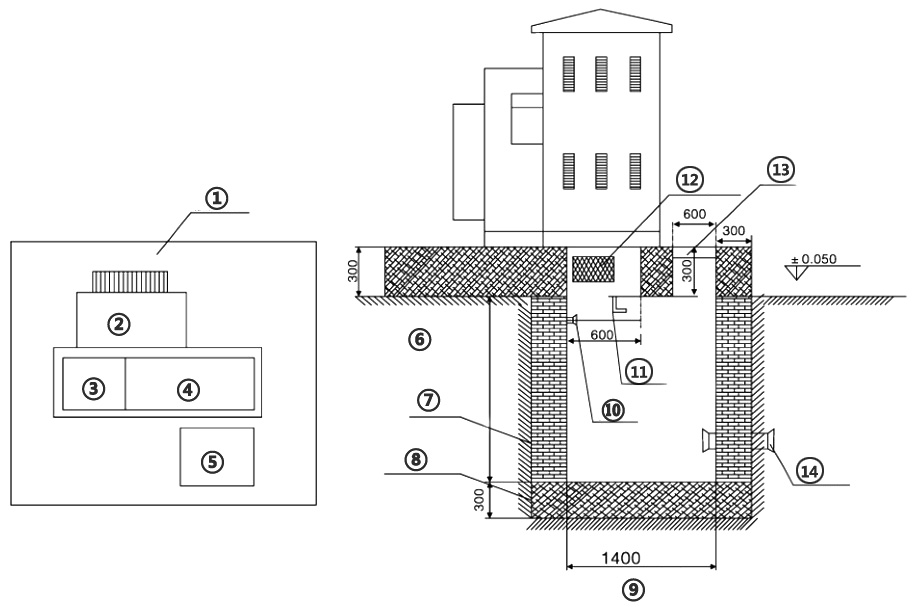
|
① heat sink |
⑥ Cable trench height |
⑪ Cable fixing bracket 50×50 angle steel |
|
② Transformer location |
⑦ Red brick wall |
⑫ Shutters |
|
③ High pressure chamber |
⑧ RC |
⑬ Movable cover |
|
④ Feeder room |
⑨ Cable trench height |
⑭ Cable hole |
|
⑤ Cable sinking |
⑩ Ground bar 25×5 flat steel |