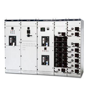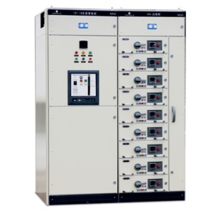
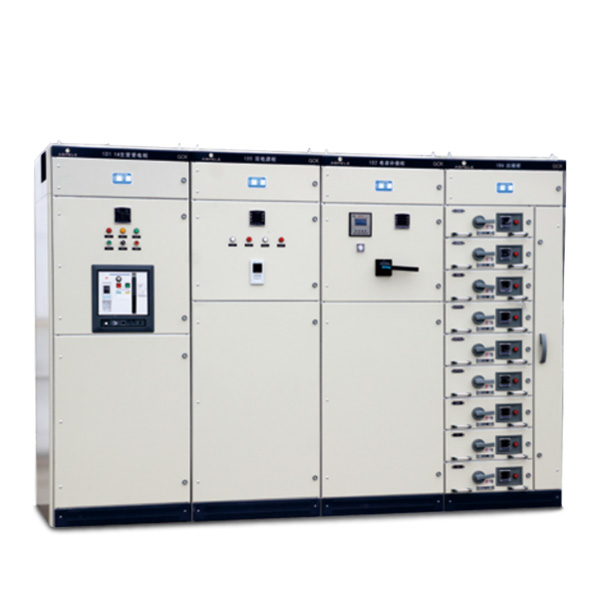
GCK low-voltage pull-out switchgear
Overview
· GCK low-voltage withdrawable switchgear is widely used in power plants, metallurgical steel rolling, petrochemical industry, light industrial textiles, port terminals, building hotels and other places as AC three-phase four-wire or five-wire system, voltage 380V, 660V, frequency 50Hz, rated The power distribution system and the centralized control of the motor in the power supply system with a current of 5000A and below.
· GCK is a comprehensive type test and has obtained CCC certification. It is an assembled high-level low-voltage switchgear designed to meet the following standards:
· National standard GB7251.1-2005 “Low-voltage switchgear”
· International standard IEC60439.1-1992 “Low-voltage switchgear and control equipment”
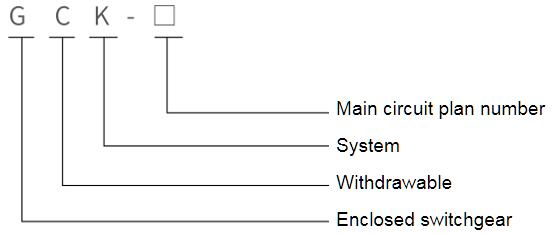
Model meaning
Normal operating conditions
♦ Ambient air temperature is not higher than +40℃, not lower than -5℃, and the average temperature is not higher than +35℃ within 24 hours;
♦ The relative temperature does not exceed 50% at the maximum temperature of +40℃, and the higher relative temperature is allowed at the lower temperature, such as 90% at +20℃;
♦ Clean air, no corrosive and explosive gas, no conductive and dust that can destroy insulation:
♦ In the absence of significant shaking and shock vibration, vertical installation, the inclination should not be greater than 5 degrees;
♦ Altitude does not exceed 2000 meters;
♦ The switchgear is suitable for transportation and storage at the following temperatures:-25℃ to +55℃, within a short time (not more than 24 hours) not exceeding +70℃;
♦ Users should consult with the manufacturer if they cannot meet the above conditions.
Main technical parameters
♦ Rated insulation voltage 660V/1000V
♦ Rated working voltage 400V/660V
♦ Rated working voltage of auxiliary circuit: AC 380V, 220V, DC 110V, 220V
♦ Bus rated current: 1000A, 1250A, 1600A, 2000A, 2500A, 3200A, 4000A, 5000A
♦ Bus rated short-time withstand current: 50kA, 80kA (effective value) for 1 second
♦ Bus rated peak withstand current: 105kA/0.1s, 140kA/0.1s, 176kA/0.1s
♦ Rated current of branch bus: 630A, 1000A, 1250A, 1600A
♦ Rated short-term withstand current of branch bus: 30kA, 50kA (effective value) for 1 second
♦ Rated peak withstand current of branch bus: 63kA, 105kA/0.1s
♦ Shell protection level: IP30, IP40
♦ Bus setting: three-phase four-wire system, three-phase five-wire system
♦ Operation mode: local, remote, automatic
Classification of switchgear
The basic cabinet frame of GCK is a combined assembly structure. All structural parts of the cabinet frame are galvanized and sprayed. They are connected to each other by screws to form a basic cabinet frame. Doors, baffles, partitions and drawers are added as needed , Mounting brackets, busbars, electrical components and other parts, assembled into a complete control center cabinet, the cabinet structure has the following characteristics:
♦ Cabinet
The cabinet frame is assembled with C-shaped materials. The cabinet frame parts and special supporting parts are supplied by our company to ensure the accuracy and quality of the cabinet body.
◇The molding size, opening size and equipment interval of the parts are modularized (modulus E=20mm, the same below).
◇The internal structural parts are galvanized.
◇The top cover of the cabinet is detachable, and the four corners of the top of the cabinet are equipped with lifting rings for lifting and shipping.
◇Cabinet is divided into bus bar room, functional unit room and cable room three mutually isolated sections to prevent the spread of accidents.
♦ Function unit (drawer part)
◇The height modulus of the drawer unit is 200mm, divided into five size series of 1/2 unit, 1 unit, 1.5 unit, 2 units, 3 units. The unit circuit rated current is 630 A and below.
◇Each MCC cabinet can install 9 drawers of 1 unit or 18 drawers of 1/2 unit at most.
◇The operating mechanism is mechanically interlocked with the drawer. When the main switch is in the closed position, the drawer cannot be withdrawn.
◇The operating mechanism of the drawer can be locked in the closing or opening position with a padlock, which can safely maintain the electrical equipment.
◇The back of the functional unit has the main circuit inlet and outlet plugs and auxiliary circuit secondary plugs.
◇The functional unit compartment is separated by a metal partition.
◇Drawer unit adopts rotary propulsion mechanism, with three-position function, simple and reliable operation.
◇ The GCK drawer propulsion mechanism adopts a spiral trajectory to move along the positioning member to realize the advancement and extraction of the functional unit. During the advancement and extraction of the functional unit, the three-position display and mechanical interlock are realized and equipped with a micro switch. Interlock.
Installation and Use
After the product arrives at the place of receipt, first of all, it should be checked whether the packaging is intact, and if any problem is found, the relevant department of the contract should be notified in time to make business records, jointly analyze the reasons for the visa, and deal with it afterwards.
For products that are not installed immediately, they should be placed in an appropriate place and properly stored according to the normal use conditions and the requirements for temporary storage of electrical equipment.
♦ The installation of the product should be carried out according to the installation diagram. The base channel steel and the bolts when bolting is used are prepared by the user. When the main busbar is connected, if the surface is uneven due to transportation, storage, etc., it needs to be smoothed before connecting and tightening.
♦ When the equipment is installed alone or in a row, the verticality, the unevenness of the cabinet surface and the deviation of the gap between the cabinets should meet the requirements of Table 1.
|
Serial number |
Name |
Allowances (mm) |
|
|
1 |
Perpendicularity |
3.3 |
|
|
2 |
Level |
Top of two adjacent cabinets |
2 |
|
Top of cabinets |
5 |
||
|
3 |
Unevenness |
Adjacent sides |
1 |
|
Line cabinets |
5 |
||
|
4 |
Joint between cabinets |
|
2 |
♦ Inspection and test before product put into operation after product installation.
◇Check whether the cabinet finish paint or other covering materials (such as spray plastic) are damaged, whether the cabinet is dry and clean, and whether the installation screws of each part are loose.
◇Whether the operating mechanism of electrical components is flexible, and there should be no stagnation or excessive operating force.
◇ Whether the on and off of the main electrical appliances are reliable and accurate.
◇Drawer or draw-out mechanism should be flexible, light, free of jamming and collision.
◇The center line of the dynamic and static contacts of the drawer or withdrawable structure should be consistent, and the contact should be tight. The insertion depth of the main and auxiliary contacts should meet the requirements. The mechanical interlocking or electrical interlocking device shall act correctly, and the locking or releasing shall be reliable.
◇The drawer with the same plan, second principle and same drawer size should be easily interchangeable without jamming or collision.
◇When replacing the fuse core, it should meet the requirements of engineering design.
◇The setting value of protection should be set correctly according to the actual load.
◇Insulation resistance value measured with 1000V megohmmeter shall not be lower than 10MΩ.
◇The connection of each bus bar should be good, and the installation of insulating supports, mounting parts and other accessories should be firm and reliable.
♦ Precautions for use
◇The equipment is a low-voltage distribution cabinet that is not installed against the wall, is operated on the front, and is maintained on both sides. The maintenance channel and door of the cabinet must only be accessed or opened by qualified professionals for operation, inspection and maintenance.
◇After connecting the cable, the bottom of the switch cabinet should be closed to prevent small animals from climbing into the cabinet and causing a short circuit accident.
◇After multiple opening and closing of air circuit breakers and molded case circuit breakers, especially after short circuit opening and closing, local contact burns and carbon materials will be generated, and the contact resistance will increase. Maintenance and repair.
◇After installation and maintenance, the isolation between the compartments and functional units must be strictly checked to ensure the good functional separation of the device and prevent the expansion of failures.
♦ Drawer operation
◇Operation of 1/2 unit drawer
The operating mechanism of the drawer is composed of a rotating part, a rotating shaft, a lock catch, etc., and has functions of opening and closing, testing, isolation and locking of the switch. The operating mechanism is also equipped with a micro switch, which is used for electrical blocking.
Working position: the main switch is closed, the main circuit and the control circuit are connected, and the functional unit is locked. “Opening position”: The main switch is open, the control circuit is connected, and the functional unit is locked.
Test position: The main switch is opened, the main circuit is disconnected, the control circuit is connected, and the functional unit is locked.
Isolation position: drawer draws out 30mm. The main and control circuits are isolated and disconnected, and the drawer is locked.
Withdrawal position: The main circuit and the control circuit are disconnected, and the drawer can be withdrawn at will.
After the operating handle is depressed by 6mm, it can be turned from (O) position to (I) position.
Working process: In the “drawing position”, the drawer can be pushed or pulled out. After turning counterclockwise by 45°, the drawer can automatically reach the “isolated position” when it is pulled out. Turn 45° clockwise to reach the “test position”. Then turn it 45° clockwise to reach the “switch off position”. After pressing the handle down 6mm and turning it 90° clockwise, the switch is closed, if you need to exit, then reverse the operation in turn. If necessary, a padlock can be added on the operating handle to open, test and isolate the main switch as a safety protection.
◇Operation of drawers of unit and above
Test: The main switch is opened, the main circuit is disconnected, the control circuit is connected, and the functional unit is locked. Separation: The main switch is opened, the main circuit is disconnected, the control circuit is disconnected, and the drawer is withdrawn at will. Connection: The main circuit plug-in and control circuit plug-in can be opened and closed, and the functional unit is locked. l: The circuit breaker is closed; O: The circuit breaker is opened.
Operating instructions: Adjust the drawer advancement mechanism to the “disengaged” position, use the “hexagonal operating handle” to rotate clockwise to the “connected” position, rotate the operating handle clockwise by 90°, the circuit breaker closes; the opening operation sequence is the same as above in contrast.
Note: 1. The propulsion mechanism cannot close the circuit breaker in the test position and the separation position.
2. When the switch is in the closed position, the propulsion mechanism cannot be operated.
♦ Unlocking mechanism
There is a round hole in the lower right corner of the drawer of unit 1 and above. This is the unlocking mechanism of the drawer door. When the drawer advancement mechanism is in the connected position and the switch handle is in the “O” position, first pull out the small cover and use a small screwdriver Insert the hole and move the lock downward to open the door. After closing the door, be sure to cover the small plastic cover, otherwise it will destroy the original protection level.
Factory Information and Accessories
| The manufacturer should provide the following documents and accessories when supplying |
| ◆ Shipping list ◆ Product certificate and factory test report ◆ Instruction Manual ◆ Related electrical drawings ◆ Main component manual ◆ Cabinet key, operating handle and spare parts specified in the contract. |
Order Notes
When ordering, the user should provide:
♦ Main circuit distribution system diagram and plane layout diagram, rated working voltage, rated working current, protection device setting current and necessary technical parameters.
♦ Indicate the cable specifications of incoming and outgoing lines.
♦ The model, specification and quantity of the main electrical components in the switch cabinet.
♦ If a bus bridge or bus duct is required between switch cabinets or incoming cabinets, the specific requirements such as span and height from the ground shall be indicated.
♦ When the switch cabinet is used in special environmental conditions, it should be explained in detail when ordering.
♦ Surface color of switchgear and other specific requirements.
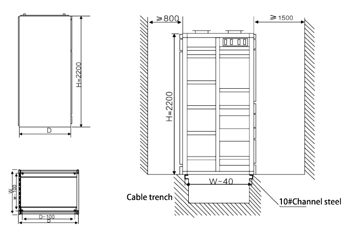
Size and Installation
♦ See the table below for dimensions
♦ Installation The GCK series switchgear is installed vertically against the wall. The back is the cable outlet of the cabinet. For easy maintenance, the back is usually 800-1200mm away from the wall. See the figure below for frontal installation.