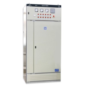
XL-21 power distribution cabinet
Overview
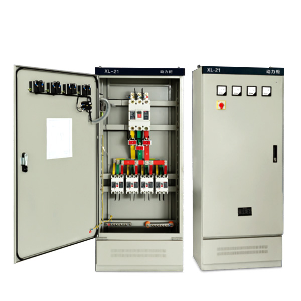
XL-21 type low-voltage power distribution cabinet is suitable for power plants and industrial and mining enterprises. It is used for power distribution in three-phase four-wire or three-phase five-wire system with AC voltage of 500 volts or less o XL-21 type low-voltage power distribution box is installed against the wall and overhauled before screen.
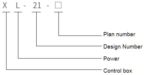
Model meaning
Structural characteristics
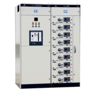
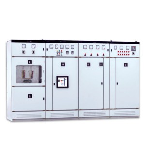
XL-21 type low voltage power distribution cabinet is closed, the shell is made of steel plate bending, and the knife switch operation handle is installed in the upper part of the right column in front of the box, which can be used as the switching power supply. The front of the distribution box is equipped with a voltmeter indicating the voltage of the bus bar. There is a door in front of the distribution box, after the door is opened, all the equipment in the distribution box is open and open, which is convenient for maintenance and repair. All distribution boxes
Adopt domestic self-designed type components, with compact structure, easy maintenance, line scheme can be flexible combination and other characteristics. In addition to air circuit breakers and fuses as short circuit protection, the distribution box is equipped with contactors and thermal relays, and the front door of the box can be fitted with operation buttons and indicator lights.
Normal operating conditions
♦ ambient temperature :-50°C〜+40 fences, and the average temperature within 24 h does not exceed +36 C;.
♦ altitude: not exceeding 2000 m;
♦ relative humidity: no more than 50% at ambient air humidity of +40 C;
There can be a higher relative humidity at lower humidity (e.g .90% at 20°C +), taking into account that changes in temperature allow for moderate frosting :
♦ the inclination of the equipment to the vertical surface should not exceed 5° when installed, the equipment should be installed in a place free of severe vibration, shock and corrosion.
Use, maintenance and repair
After the power distribution box is installed or overhauled, the following inspections and tests must be carried out before it is put into operation (the inspections and tests after overhaul, depending on the quality of their overhaul)
♦ Check whether the electrical equipment installed in the power distribution cabinet and the secondary wiring meet the requirements of the drawings.
♦ Check whether the knife switch and air switch used for operation are flexible, and there should be no jamming.
♦ Check whether the electrical equipment installed is in good contact and meets the requirements of the electrical equipment itself.
♦ Check whether there are other foreign objects inside the power distribution cabinet and whether the solid screws of each part are loose.
Technical parameters of major equipment
Knife melting combination switch
|
Type |
Current rating (A) |
Flame rated current (A) |
Remarks |
|
HR3-400/34 |
400 |
150,200,250,300,350,400 |
No melt installed with isolating blade |
Current transformer
|
Type |
Current rating (A) |
(A) |
Remarks |
|
LM-0.5 |
75.100、150、200、300、600 |
5 |
fuses
| Type | fuses | Fuse rated current (A) | Remarks |
| RL1-15 | 15 | 2.4、5、6、10、15 | |
| RL1-60 | 60 | 20.25、30、35、40、50、60 | |
| RL1-100 | 100 | 30.40,50,60,80 s 100. | |
| RL1-200 | 200 | 80.100、120、150、200 | |
| RL1-400 | 400 | 150.200、250、300、350、400 |
Ac Contactors
| Type | Current rating (A) | Draw coil voltage (V) | Remarks |
| CJ10-10 | 10 | ||
| CJ10-20 | 20 | Exchange | |
| CJ10-40 | 40 | 110 | |
| CJ10-80 | 80 | 220 | |
| CJ10-150 | 150 | 380 |
Order Notes
Customer should provide the following information when ordering:
♦ sub-line scheme and single line system diagram;
♦ secondary line expansion system diagram;
♦ detailed specifications and data of all kinds of electrical equipment in each case;
♦ shall provide the layout plan and layout plan of power distribution cabinet when ordering B type structure.

