
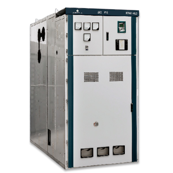
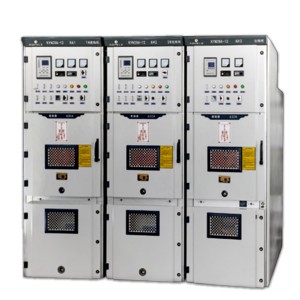
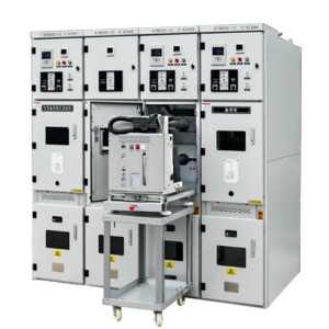
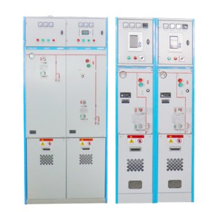
KYN61-40.5(Z) armored removable AC metal enclosed switchgear
Overview
KYN61-40.5(Z) armored removable AC metal closed switchgear (hereinafter referred to as switchgear) is a three-phase AC 50 Hz, rated voltage 40.5 kV indoor complete distribution equipment. As a power plant, substation and industrial and mining enterprises to accept and distribute electricity. It can also be used for frequent operation.
This switchgear meets GB/T11022-1999.GB3906-1991 and DL404-1997 standards.
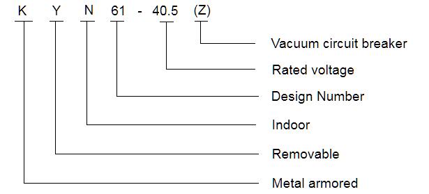
Model meaning
Normal operating conditions
♦ Ambient air temperature:maximum temperature + 40℃, minimum temperature -15 ℃.
♦ Relative humidity: daily average relative humidity :95%,
♦ Average daily water vapor pressure shall not exceed 2.2 kPa;
♦ Monthly average relative humidity:≤ 90%,
♦ Average monthly water vapour pressure shall not exceed 1.8 kPa;
♦ Altitude: below 2000 m.
♦ Seismic intensity: no more than 8 degrees.
♦ Surrounding air should be free from corrosive or combustible gases, water vapor and other obvious pollution.
♦ No violent vibration place.
♦ In excess of the normal conditions prescribed by the GB3906, the user and the manufacturer shall consult
Main features
♦ Cabinet structure adopts assembly type, circuit breaker adopts handcart floor type structure;
♦ It is equipped with a new type of composite insulated vacuum circuit breaker, and has the characteristics of good interchangeability and simple replacement.
♦ The handcart frame is equipped with a screw nut pushing mechanism, which can easily move the handcart and prevent the pushing structure from being damaged by misoperation;
♦ All operations can be carried out under closed cabinet doors;
♦ Interlocking between the main switch, handcart and switchgear door adopts mandatory mechanical locking mode to meet the “five prevention” function;
♦ Cable room has ample space to connect multiple cables;
♦ Fast grounding switch for grounding and circuit short circuit;
♦ Protection level of the shell IP3X, the hand-car compartment door-stripping state, IP2X; protection level
♦ Products meet the GB3906-199K DL404-1997 and refer to the adoption of international IEC-298 standards.
Main technical parameters of vacuum circuit breaker
|
Name |
Unit |
Numerical value |
|
Rated voltage |
kV |
40.5 |
|
Rated frequency |
Hz |
50 |
|
Rated power frequency withstand voltage |
kV |
95/1 min |
|
Rated lightning impulse withstand voltage |
kV |
185 |
|
Rated current |
A |
1250 1600 2000 |
|
Rated Short-time withstand current |
kA |
20 25 31.5 |
|
Rated short-time on-off current |
kA |
20 25 31.5 |
|
Rated peak withstand current |
kA |
50 63 80 |
|
Rated short continuous current |
ms |
4 |
|
Opening Time |
ms |
30 ≤ t ≤ 60 |
|
Closing Time |
s |
50 ≤ t ≤ 100 |
|
Rated short-circuit breaking current times |
Third |
20 |
|
Mechanical life |
Third |
10000 |
|
Protection level |
IP43 |
Main technical parameters of vacuum switchgear
| Name | Unit | Numerical value |
| Rated voltage | kV | 40.5 |
| Rated current | A | 1250 1600 2000 |
| Rated frequency | Hz | 50 |
| Rated short-time withstand current | kA | 20 25 31.5 |
| Rated peak withstand current | kA | 50 63 80 |
| Rated power frequency withstand voltage | kV | 95/1min |
| Rated lightning impulse withstand voltage | kV | 185 |
| Rated short-circuit duration | s | 4 |
| Protection level | IP3X |
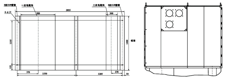
Shape dimensions
|
Height |
2650 |
|
|
Width |
Rated Current 1600 A and below |
1400 |
|
Depth |
Cable incoming and outgoing line |
2870 |
|
Overhead incoming and outgoing line |
2950 |
Main technical parameters of spring operating mechanism
| Item | Unit | Value | |
| Rated operating voltage | Opening coil | v | DC220/110,AC220/110 |
| Closing coil | |||
| Rated operating current | Opening coil | A | 0.96(220V),1.05(110V) |
| Closing coil | |||
| Energy storage motor power | W | 230 | |
| Rated voltage of energy storage motor | V | DC220/110,AC220/110 | |
| Energy storage time | S | ≤12 | |
Switchgear installation
a. Height of electrical room: ≥ 4500mm;
b. Distance from the wall behind the cabinet: ≥ 1500mm;
c. The flatness of the basic structure: ≤ 1mm / m;
d. The part of the foundation embedded channel steel above the ground shall not exceed 3mm;
e. Can be fixed on the foundation with bolts or welding;
f. The weight of the switch cabinet is about 1800kg;
g. The width of the switchgear operation corridor (single row): ≥ 3000mm; Double-sided (face-to-face) ≥ 4000mm.
Equipment structure diagram
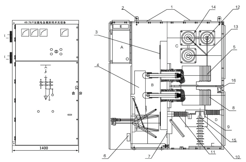
| A. Instrument room | 1. Pressure relief plate | 6. Secondary plug | 11. Grounding switch |
| B. Circuit breaker room | 2. Ring | 7. Heating device | 12. Main bus |
| C. Busbar room | 3. Valve | 8. Current transformer | 13. Support bus |
| D. Cable room | 4. Circuit breaker | 9. Cable | 14. Busbar bushing |
| E. Small busbar room | 5. Contact box | 10. Insulation partition | 15. Lightning arrester |
| 16. Lighting |
Products categories
-
KYN28A-12 armored removable enclosed switchgear
-
HXGN □ -12 Air-insulated compact switchgear
-
HXGN□-12 box-type fixed AC metal-enclosed switc...
-
XGN66-12 (Z) fixed enclosed switchgear
-
KYN550-12 indoor armored removable AC metal enc...
-
SM6-40.5 fully enclosed fully insulated inflata...