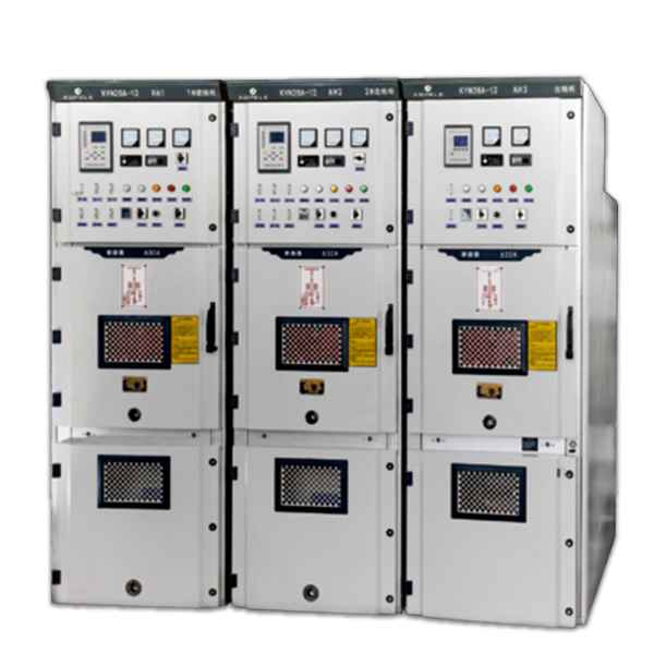
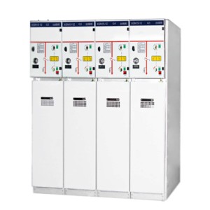
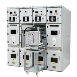
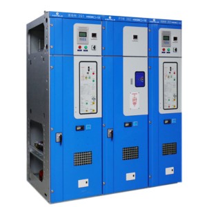
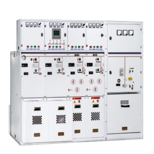
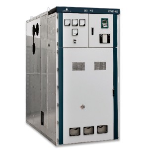
KYN28A-12 armored removable enclosed switchgear
Overview
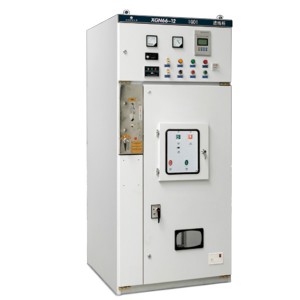
KYN28A-12 type indoor AC metal armor medium-mounted switchgear. The utility model is suitable for three-phase AC rated voltage 12 kV, rated frequency 50 Hz power system for receiving and distributing electric energy and controlling, protecting and monitoring circuits.
Meeting the criteria:
GB3906-2006《3.6〜40.5kV AC Metal Closed Switchgear and Control Equipment
General Technical Conditions for GB11022-89《 High Voltage Switchgear
IEC298(1990)《 rated voltage 1 kV above 50 kV and below AC metal closed switchgear and control equipment
DL404-97《 Technical Conditions for Ordering High Voltage Switchgear for Indoor Exchange
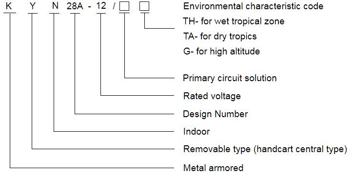
Model meaning
Functions and features
The switchgear is designed according to the armored metal enclosed switchgear in GB3906-91. The whole is composed of two parts: the cabinet body and the central extractable parts (ie, handcart)
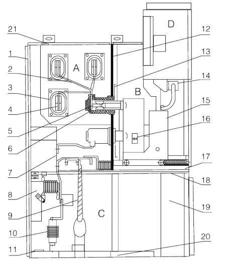
Figure ). The cabinet is divided into four separate compartments, and the protection grade of the enclosure is IP4X. When the doors of each small room and the circuit breaker room are opened, it is IP2X. With overhead access line and cable access
Lines and other functional solutions are arranged and combined to form a complete power distribution system device. The switchgear can be installed, commissioned and maintained from the front, so it can be
Back-to-back, double arrangement and wall-mounted installation improve the safety and flexibility of the switchgear and reduce the floor space.
♦ Housing and others
The main cabinet frame of the switchgear is made of aluminum-zinc thin steel plate, processed by CNC machine tools, and using multiple hemming processes, so that the entire cabinet is not only highly precise
The advantages of anti-corrosion and anti-oxidation, and because of the multiple folding process, the cabinet is lighter in weight, higher in mechanical strength and beautiful in appearance than other similar equipment cabinets. cabinet
The body adopts an assembled structure, which is formed by connecting rivet nuts and high-strength bolts, which makes the processing cycle short, the parts versatile, the area occupied is small, and it is easy to organize production.
♦ Handcart
The skeleton of the handcart is assembled from thin steel plates processed by CNC machine tools. The handcart and the cabinet are insulated and coordinated, the mechanism interlocking is safe, reliable and flexible. According to the use, the handcart can
Divided into circuit breaker handcart, voltage transformer handcart, metering handcart, isolation handcart and so on. Various types of handcarts vary according to modulus and building block type, and handcarts of the same specification can be freely exchanged 100%.
The handcart has a disconnection position, a test position and a working position in the cabinet. Each position is provided with a positioning device to ensure the reliability of the interlock. It must be operated according to the interlock anti-misoperation procedure.
All kinds of handcarts use nuts and screw rods to advance and withdraw. Their operation is light and flexible, which is suitable for operation by duty personnel. When the handcart needs to remove the cabinet, use a special
The transfer truck can be easily drawn out for various inspections and maintenance; and the central type is adopted, the entire handcart is small in size, and the inspection and maintenance are extremely convenient.
♦ Compartment
The main electrical components of the switchgear have their own independent compartments, namely: circuit breaker handcart room, busbar room, cable room, and relay instrument room. The protection level of each compartment is reached
IP2X; except for the outdoor of the relay, the other three compartments have their pressure relief channels respectively. Due to the use of a central type, the cable room space is greatly increased, so the equipment can be connected to multiple cables.
a. Circuit breaker compartment
Rails are installed on both sides of the isolation for handcart 15 to move from the disconnected position and the test position to the working position in the cabinet. The partition 13 (shutter) of the static contact box 6 is installed in
Behind the rear wall of the handcart room. When the handcart moves from the disconnected position and the test position to the working position, the shutters on the upper and lower static contact boxes are linked with the handcart and are automatically opened at the same time;
When moving in the opposite direction, the shutter automatically closes until the trolley is retracted to a certain position and completely covers the static contact box, forming an effective isolation. Since the upper and lower valves can be operated separately,
During maintenance, the live valve can be locked to ensure that the maintenance personnel do not touch the live body. When the breaker room door is closed, the handcart can also be operated through the middle door
The observation window can observe the location, closing position and energy storage status of the handcart in the compartment.
b. Busbar compartment
The main busbar 4 is a single splicing interpenetrating connection. It is fixed by support bus 2 and static contact box. The main busbar and the connecting busbar are rectangular cross-section copper bars, used for large current negative
Double-root busbars are used to make up the lotus. The support bus is connected to the static contact box 6 and the main bus by bolts, and no other support is needed. For special needs, heat-shrinkable tubing and
The insulation cover and end caps of the connection bolts are covered, and the busbars of adjacent cabinets are fixed with bushings 3. In this way, the air buffer reserved between the busbars can be used in the event of an internal fault arc.
To prevent it from melting, the casing 3 can effectively limit the accident to this cabinet without spreading to other cabinets.
c. Cable compartment
The switchgear adopts a central type, so the cable room has a large space. The current transformer 7 and the grounding switch 8 are installed on the rear wall of the compartment, and the lightning arrester 10 is installed on the lower part of the rear of the compartment.
After opening the lower door of the cabinet, the construction personnel can enter the cabinet for installation and maintenance from below. The cable connecting conductors in the cable compartment can be combined with 1 to 3 single-core cables per phase. When necessary
It can be connected with 6 single-core cables in parallel, and the bottom of the cabinet connecting the cables is equipped with a slotted removable non-metallic sealing plate or a non-magnetically conductive metal sealing plate to ensure the convenience of construction.
d. Relay instrument room
The relay instrument room can be installed with relay protection components, instruments, live monitoring indicators, and secondary equipment with special requirements. The control wire is laid in a wire slot with sufficient space,
And there is a metal cover plate, which can isolate the secondary line from the high voltage room. The left side of the trunking is reserved for the introduction and extraction of small busbars. The control wires inside the switchgear itself are laid in
On the right side, there is a small busbar passing hole for easy construction on the top plate of the relay instrument room. When wiring, the top cover plate of the instrument room can be turned over, which is convenient for the installation of small bus bars.
♦ Interlocking device for preventing misoperation
The switchgear has a reliable interlocking device, which fully meets the requirements of “five preventions”.
a. There is a prompt button or KK type transfer switch on the door of the instrument room to prevent accidental closing and accidental opening of the circuit breaker
b. When the circuit breaker handcart is in the test or working position, the circuit breaker can only perform the closing operation, and after the circuit breaker is closed, the handcart cannot move, preventing the wrong push and pull with load
breaker.
c. Only when the earthing switch is in the open position, the circuit breaker trolley can be moved from the open and test position to the working position. Only when the circuit breaker handcart is in the test, open position,
The grounding switch can only perform the closing operation (the grounding switch can be equipped with a voltage display device).
Close the circuit breaker when closed.
d. When the grounding switch is in the open position, neither the lower door nor the rear door can be opened, preventing accidental entry into the live interval.
e. The circuit breaker handcart is indeed in the test or working position, and when there is no control voltage, it can only be opened manually, not closed.
f. When the circuit breaker trolley is in the working position, the secondary plug is locked and cannot be removed.
g. Each cabinet can be equipped with electrical interlock.
The switchgear can also be equipped with an electromagnetic lock locking device on the grounding switch operating mechanism to improve reliability, and its order is selected according to user needs.
♦ pressure relief device
In the circuit breaker handcart room, busbar room and cable room are all equipped with pressure relief devices. When an internal fault arc occurs in the circuit breaker or busbar, with the occurrence of the arc, the switch cabinet
The internal air pressure increases, and the special sealing ring installed on the door closes the front. The pressure relief metal plate equipped on the top will be automatically opened to release the pressure and discharge gas to ensure
Keep operators and switch cabinets safe.
Main technical parameters of vacuum circuit breaker
|
Projects |
Unit |
Value |
|
|
Rated voltage |
kV |
3.6、7.2、12 |
|
|
Rated frequency |
Hz |
50 |
|
|
Circuit breaker rated current |
A |
630.1250、1600、2000、2500、3150 |
|
|
Switchgear rated current |
A |
630.1250、1600、2000、2500、3150 |
|
|
rated short-time withstand current (4 S) |
kA |
16,20,25,31-5,40,50 |
|
|
Rated peak tolerance current (peak) |
kA |
40,50,63,80,100,125 |
|
|
Rated short circuit switching current |
kA |
16,20,25,31.5,40,50 |
|
|
Rated short-circuit closing current (peak) |
kA |
40,50,63,80,100,125 |
|
|
rated insulation level |
1 min Power frequency withstand voltage
|
kV |
24.32、42 |
|
Lightning Shock Tolerance Voltage |
kV |
40.60、75 |
|
|
Protection level |
The shell is IP4X, compartment and the IP2X. is when the door of the circuit breaker is broken |
||
Normal operating conditions
♦ ambient air temperature: maximum temperature +40°C. Minimum temperature: C.15
♦ relative humidity: daily average relative humidity :95%; daily average water vapour pressure not exceeding 2 KPa;2 months average relative humidity: w 90%; monthly average water vapour strength not exceeding 1.8 KPa;
♦ altitude: below 1000 m.
♦ seismic intensity: no more than 8 degrees.
♦ surrounding air should be free from corrosive or combustible gases, water vapor and other obvious pollution.
♦ no violent vibration place.
♦ use beyond the normal conditions specified in the GB3906, the user and the company to negotiate.
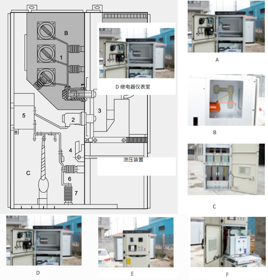
Schematic diagram of switchgear structure
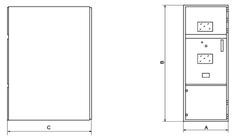
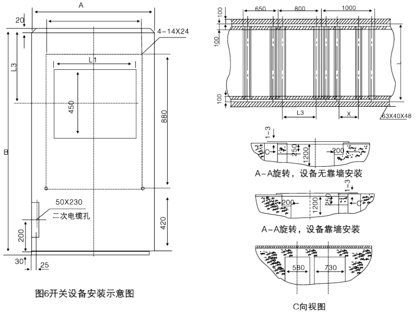
Installation dimensions
| A cabinet width | B cabinets | L1 | L2 | L3 | L4 |
| 800 | 1500 Cable | 530 | 630 | 150 | 490 |
| 800 | 1660 Overhead | 530 | 630 | 310 | 650 |
| 800 | 1500 Cable | 730 | 830 | 150 | 490 |
| 1000 | 1660 Overhead | 730 | 830 | 310 | 650 |
| Height | 2300 | |
| Width | rated current A 1250 and below | 800 |
| Current rating 1600 A and above | 1000 | |
| Depth | Cable feed line | 1500 |
| Airline | 1660 | |
Switch cabinet dimensions
A handcart
♦ The frame of the handcart is made of thin steel plate, processed by CNC machine tools, riveted and welded. According to usage, handcarts can be divided into circuit breaker handcarts, voltage transformer handcarts, isolated handcarts,
♦ For measuring handcarts, etc., handcarts of the same specifications can be easily interchanged. The handcart has an isolation position, a test position and a working position in the cabinet. Each position is equipped with a positioning device to ensure that
♦ The handcart cannot move casually when it is in the above position, and the interlock must be released when moving the handcart.
B Busbar room
♦ The bus bar is led from one switch cabinet to another switch cabinet, and is fixed by the branch bus bar and the static contact box. The flat branch bus is connected to the static contact box and the main bus by bolts,
♦ No other wire clips or insulators are needed. When users and projects have special needs, the connection bolts on the bus bar can be encapsulated with insulation and end caps. Crossing the switch on the bus
♦ When the cabinet partition is fixed with busbar bushing. If an internal fault arc occurs, it can limit the spread of the accident to the adjacent cabinet and protect the mechanical strength of the bus.
C Cable room
The current transformer, grounding switch, lightning arrester and cable can be installed in the cable room, and a slotted removable aluminum plate is prepared at the bottom to ensure convenient construction on site.
D Relay table room
♦ The relay instrument room is used to install various relays, instruments, signal indications, operation switches and other components. In addition, a small busbar room can be added on top of the instrument room according to user requirements.
♦ Sixteen-way control small bus can be laid.
E pressure relief device
♦ A pressure relief device is provided above the handcart room, bus bar room, and cable room. When an internal fault arc occurs in the circuit breaker or main bus bar, cable room, accompanied by the occurrence of the arc,
♦ The air pressure inside the switchgear rises, after reaching a certain pressure, the pressure release metal plate of the top device will be automatically opened to release the pressure and discharge the gas to ensure the operator
♦ And switchgear safety.
.F lock structure
♦ The connection between the middle door and the cabinet body adopts a lock structure and is equipped with a lifting mechanism to make the middle door more convenient to open. When the middle door is closed, its connection with the cabinet body
♦ The strength is better, and the ability to effectively combat internal arcing faults is enhanced.

