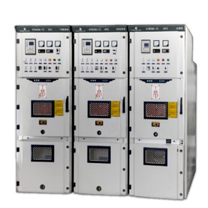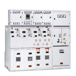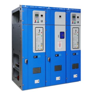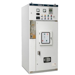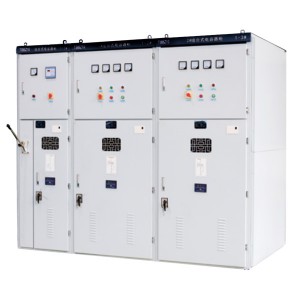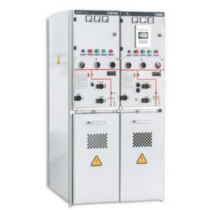
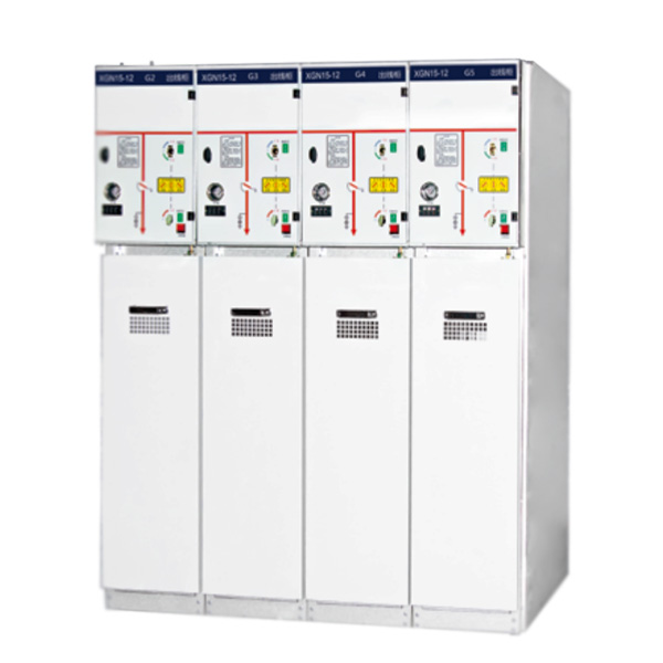
XGN15-12 box-type fixed AC metal-enclosed switchgear
Overview
XGN15-12 type AC metal closed ring switch equipment (hereinafter referred to as ring net cabinet) is a new generation of high-voltage electrical products which we design and manufacture successfully by introducing foreign advanced technology and according to the requirements of domestic agricultural power and urban network transformation. The technical performance indexes all meet the IEC62271-200:2003 and GB3906 standards.
The main switch, operating mechanism and components of the ring net cabinet shall be SFL-1 by ABB original parts of the company or domestic assembly of imported parts Switchgear type 2/24 may also be fitted with ABB company’s original HAD/US SF6. according to user needs circuit breaker or VD4-S type vacuum circuit breaker. Its operation mode is divided into dynamic and electric.
After NC machine tool machining, the cabinet is moved and connected, the protection grade is up to IP3X, and has reliable mechanical interlocking and anti-misoperation function. This product has the characteristics of small size, light weight, beautiful appearance, simple operation, long life, high parameters, no pollution, less maintenance and so on.
XGN15-12 type unit AC metal closed ring network switchgear is suitable for receiving and distributing electric energy in a power network of 50 Hz、12kV. Cabinet main switch SF6 switch
Model meaning
Main technical parameters of vacuum circuit breaker
| Serial number |
Name |
Unit | Value |
| 1 |
Rated voltage |
kV | 12 |
| 2 |
Rated frequency |
Hz | 50 |
| 3 |
Main bus rated current/fuse maximum rated current |
A | 630,125 |
| 4 |
Main circuit, ground circuit rated short time tolerance current |
kA/s | 20,3 |
| 5 |
Main circuit, ground circuit rated peak tolerance current |
kA | 50 |
| 6 |
Main circuit, ground circuit rated short circuit closing current |
kA | 50 |
| 7 |
Full capacity open-off of load switch |
Third | 100 |
| 8 |
fuse opening current |
kA | 31.5,40 |
| 9 |
Rated closed loop open current |
A | 630 |
| 10 |
Rated transfer current |
A | 1600 |
| 11 |
Mechanical life |
Third | 2000 |
| 12 |
1 min Power frequency withstand voltage (peak) relative, ground/isolated fracture |
kV | 42,48 |
| 13 |
Lightning impulse withstand voltage (peak) interphase, ground/isolated fracture |
kV | 75,85 |
| 14 |
Secondary circuit 1 min power frequency withstand voltage |
kV | 2 |
| 15 |
Protection level |
IP3X |
Functions and Features
◆ Cabinet structure
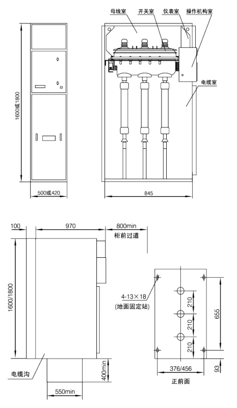
The ring net cabinet is made of 2mm thick aluminum-zinc plate (or after cold-rolled plate is sprayed) riveted and formed. There are two pressure relief holes behind the cabinet. One is for the cable compartment and the other is for the load switch/busbar compartment. This structure can guarantee the reliability of personal installation and operation equipment to the maximum extent.
◆ Each compartment
◇ Busbar room
The busbar room is located at the top of the cabinet and connected to the adjacent switch cabinet.
◇ The load switch is an independent unit filled with SF6 gas.
◇ Cable room
About 75% of the space is used for cable connections, fuses, grounding switches, and CT and PT installations.
◇ Institutional cell and interlock
The cell contains the operating mechanism and mechanism interlock as well as position indication, auxiliary contacts, trip coil, live display and interlock.
◇ Relay box
The relay box is on the top of the cabinet and is optional. The cell is used to install special devices such as meters, relays and motor units.
◇ Circuit breaker room
A circuit breaker (SF6 or vacuum) can be placed under the load switch.
◆ Pressure relief
◇ Pressure release above
The above is used to release the gas pressure generated during the arc accident inside the busbar and load switch room.
◇ Pressure relief below
The following is used to release the gas pressure generated during the arc accident inside the cable compartment.
◆ SFL load switch (ABB original parts)
The SFL load switch is a double-breakpoint, rotating dynamic contact, using SF6 gas as the arc extinguishing medium, and the dynamic and static contacts are placed in a reinforced structured molded epoxy resin shell. At the leading end of the operating shaft is a transparent hot-pressed plastic end cap, the status can be observed through the end cap. Each switch is permanently sealed after being filled with SF6 gas at a pressure of 1.4 bar (SFL means “always sealed”). A helium detector can be used to check for gas leaks. The vertical or horizontal installation of the switch is not limited. In the unit cabinet, the typical installation method is to place a steel partition between the cable room and the busbar room for horizontal installation. This installation method seals the switch housing in a grounded steel plate and isolates the busbar from the cable joint to meet the most stringent safety requirements for operation and maintenance. If arcing occurs inside, there is a weak point in the structure at the rear of the enclosure, it will be flushed away, and the arc gas will be led out of the switch, then the arc valve on the cabinet will be flushed out and the overpressure gas will be directed out of the cabinet.
◆Optional equipment-auxiliary contact 2 normally closed 2 normally open + extended 2 normally open 2 normally closed-shunt trip coil for SFL with A mechanism.
◆Select the switch of K mechanism SFL12/17.5 IVDP575305RI SFL24K IVDP575304RI
◆Select the switch of mechanism A SFL12/17.5 IVDP575303RI SFL24A IVDP575302RI
◆ VD4-S vacuum circuit breaker (ABB original parts)
VD4-S type vacuum circuit breaker is specially designed for unit switchgear, and its breaking capacity is enough to cope with various conditions, including the operation of normal switching equipment or branch network and breaking short circuit under special circumstances. Vacuum circuit breakers are particularly suitable for networks that frequently operate within the operating current range. The VD4-S vacuum circuit breaker is equipped with a spring operating mechanism and has a reclosing function (open-0.3s-close-open-180s-close), and has reliable operation and long service life. The whole circuit breaker includes three vacuum switch bulbs, and the exterior is a resin insulated cylinder with a vertical structure. The extinction of the arc is the result of the forced displacement of the arc due to the spiral groove of the arc extinguishing contact. Since the minimum static vacuum in the switch insulation cylinder is 10-4 to 10-8 bar, so even though there is relatively little gap between the switch contacts, a high dielectric strength can be obtained. The arc extinguishes at the first zero point of the short-circuit current. Due to the small contact gap, the high conductivity of the metal gas plasma at the arc voltage drop, and the short arcing time, the arc energy is extremely low, which is beneficial to the extension of the contact and even the entire switch life.
Standard equipment-manual operation
-Electric operation
-Auxiliary contact 2 normally open 2 normally closed
-Shunt trip with position contacts
-Shunting and closing coil
Optional equipment-S5 or PR512 overcurrent relay
-Low voltage release
-Interlocking coil
Circuit breaker model
VD41206-20S
VD41706
VD42406
◆ HAD/US type SF6 circuit breaker (ABB original parts)
The HAD/US type SF6 circuit breaker is specially designed for ring network switchgear, and its breaking capacity is sufficient to cope with various conditions, including the operation of normal switching equipment or branch network and breaking short circuit under special circumstances. The new generation of HAD has the latest SF6 breaking process, coupled with a simple structure and requires very little operating energy. Such a simple energy storage operating mechanism has the characteristics of long mechanical life when used. The circuit breaker adopts spring operating mechanism to realize automatic reclosing operation. The special structure of the opening and closing part of the switch can make the electrical life extension be unusually guaranteed. The switch is made into a separate column structure and placed vertically. The switch adopts the principle of self-blowing arc, that is, the arc itself is used to extinguish the arc. When the circuit breaker is opened, an arc is generated between the dynamic and static contacts in the arc extinguishing chamber. The high temperature and high ionization effect of the arc cause the pressure of the SF6 gas to rise rapidly in the arc extinguishing chamber. The gas is gradually sprayed out of the arc extinguishing chamber through the nozzle, so that the arc is thinned, cooled, interrupted, and prevented from reigniting. Therefore, the moving part of the switch requires little energy, which further improves the reliability of long-term operation.
| SFL technical data | ||||
| Rated voltage | KV | 12 | 17.5 | 24 |
| Impact pressure | KV | 75 | 95 | 125 |
| One minute power frequency voltage | KV | 28 | 38 | 50 |
| Rated current | A | 630 | 630 | 630 |
| Closing capacity | KA | 50 | 50 | 40 |
| Thermal stable current | KA/S | 20,3 | - | - |
| Opening capacity | A | 1700 | - | - |
| Maximum fuses | A | 125 | - | - |
| Polar distance | mm | 210 | 210 | 210 |
| VD4-S technical data | ||||
| Rated voltage | KV | 12 | 17.5 | 24 |
| Impact pressure | KV | 75 | 95 | 125 |
| Power frequency withstand voltage | KV | 28 | 38 | 50 |
| Rated current | A | 630 | 630 | 630 |
| Thermal stable current | KA/S | 20,3 | ||
| Polar distance | mm | 210 | 210 | 210 |
◆This switch has many advantages:
◇The arc burning duration is short, and the insulation strength in the arc extinguishing chamber recovers quickly.
◇ Even in the most demanding environment to ensure safety and reliability.
◇Can cut off the inductive and capacitive current of low value.
◇The operating mechanism is simple, can be quickly opened and closed, and the mechanical life is long.
◇Reduce the wear of contacts and arc chamber, that is, extend the electrical life.
◇Allow more operation times, but the maintenance workload is very small.
◇ Lightweight structure, compact and stable.
| Standard equipment | Optional equipment | 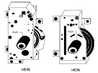 |
| - Electric operation- Manual operation- Auxiliary contacts (2 open and 2 closed)- shunt trip with positional contact- shunt closing coil- Gas pressure control at signal contacts | S5 Solid Overflow Relay- PR511-PR512 overcurrent relay- Low voltage release- interlocking ringsHAD 120625HAD 120520HAD170620HAD 170616 |
◆ K and A type operation structure (ABB original parts)
This mechanism is used to operate load switches and load switches with fuses
◇ K-type mechanism: The K-type mechanism is a single spring mechanism used for load switch on-off operation. The switch on-off is achieved by the spring energy storage through the dead point. K type mechanism can choose motor to realize electric operation.
◇ A-type mechanism: A-type mechanism double spring mechanism, one of which is used for switch closing, and the other is used for switch opening. Before the switch is closed by the closing spring, it must be placed in the energy storage state. After the closing operation, the opening is automatically placed in the energy storage state. So you can use manual, shunt trip coil or fuse striker to trip.
| Institution model -For load switch -K institution 1VDP586042R1 -For load switches with fuses -A institution 1VDP575013R1 |
Optional equipment -Motor operation on K mechanism |
| Working voltage kV | Transformer rated capacity | |||||||||||||||
| 50 | 75 | 100 | 125 | 160 | 200 | 250 | 315 | 400 | 500 | 630 | 800 | 1000 | 1250 | 1600 | 2000 | |
| Fuse selection (nominal value is ampere) | ||||||||||||||||
| 3 | 25 | 25 | 40 | 40 | 63 | 63 | 63 | 80 | 100 | 100 | 160 | |||||
| 5 | 16 | 16 | 25 | 25 | 40 | 40 | 63 | 63 | 63 | 80 | 100 | 100 | 160 | |||
| 6 | 16 | 10 | 25 | 25 | 25 | 40 | 40 | 63 | 63 | 63 | 80 | 100 | 100 | 160 | ||
| 10 | 10 | 10 | 16 | 16 | 25 | 25 | 25 | 40 | 40 | 63 | 63 | 63 | 80 | 100 | 100 | |
| 12 | 10 | 10 | 16 | 16 | 16 | 25 | 25 | 40 | 40 | 63 | 63 | 63 | 80 | 100 | ||
| 15 | 10 | 10 | 16 | 16 | 16 | 16 | 25 | 25 | 25 | 40 | 40 | 63 | 63 | 63 | 100 | |
| 20 | 10 | 10 | 10 | 10 | 16 | 16 | 16 | 25 | 25 | 25 | 40 | 40 | 63 | 63 | -63 | 80 |
| 24 | 10 | 10 | 10 | 10 | 16 | 16 | 16 | 15 | 25 | 25 | 25 | 40 | 40 | 63 | 63 | 63 |
◆ SFL-12/24 Switchgear
The main components of SFL12/24 switchgear are imported original parts. The switchgear is a double-break, three-station, rotary moving contact, with SF6 gas as the arc extinguishing medium.
The moving contact is placed in a die-cast epoxy resin shell with a reinforced structure.
Each switch is permanently sealed after being filled with SF6 gas at a pressure of 0.4bars. A helium detector can be used to check for gas leakage. The switch is vertical and horizontal installation is not limited. The typical installation method in the ring network cabinet is to place a steel plate between the cable room and the busbar room for horizontal installation. This installation method isolates the busbar and cable joints to meet the most stringent safety requirements for operation and maintenance. If there is an internal arcing, there is a structural weakness at the rear of the shell, it will be washed away. Then the arc valve above the cabinet opens and directs the overpressure airflow out of the cabinet. Optional equipment-auxiliary contact 2 normally closed 2 normally open + extended 2 normally open 2 normally closed 1 shunt trip coil for SFL with A mechanism.
Technical data
|
Rated voltage |
Unit |
12 |
17.5 |
24 |
|
Impact pressure |
KV |
75 |
95 |
125 |
|
One minute power frequency voltage |
42 |
55 |
65 |
|
|
Rated current |
A |
630 |
630 |
630 |
|
Closing capacity |
KA |
50 |
50 |
40 |
|
Thermal stable current |
KA/S |
20/3 |
- |
- |
|
Opening capacity |
A |
1700 |
- |
- |
|
Maximum fuses |
A |
125 |
- |
- |
|
Polar distance |
mm |
210 |
210 |
210 |
Shape dimensions
|
Serial number |
Name |
Unit |
Value |
| 1 |
Circuit breaker cabinet width |
mm |
750 |
| 2 |
Other cabinet width |
mm |
375,500 |
| 3 |
High |
mm |
1600,1850 |
| 4 |
Deep depth |
mm |
980,900 |
| 5 |
Relay box height |
mm |
450 |