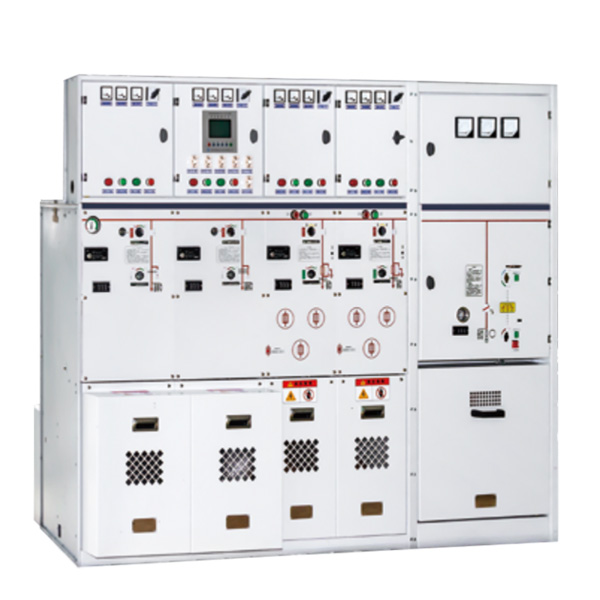
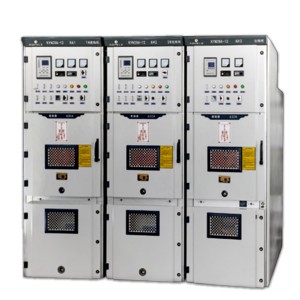
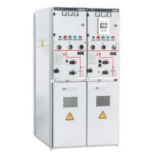
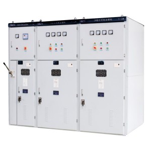
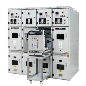
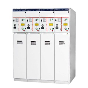
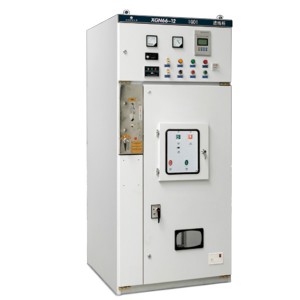
SM6-12 fully enclosed fully insulated inflatable ring network switchgear
Overview
SM6-12 series of fully enclosed fully insulated inflatable ring network switchgear is a metal common box closed switchgear SF6 gas insulation. the equipment can be composed of load switch unit, load switch fuse combination electrical unit, vacuum circuit breaker unit, bus line entry unit module. Adopt a series of advanced technology and materials, with excellent electrical and mechanical properties, small affected by the environment and weather, small volume, easy to install, easy to operate, no maintenance, Dan has a flexible combination. Clear and intuitive design to ensure simple and direct operation. feeder wiring capacity is large, suitable for a variety of wiring systems.
Unit definition
| Unit code | Meaning |
| C | Standard Single Casing Load Switching Unit |
| F | Load switch-melting combination electrical unit |
| V | Circuit breaker unit |
| D | Cable feed unit (without switch) |
| + | Busbar side casing |
| - | Busbar top casing |
| SL | Mother link unit |
| M | Metering unit |
| PT | PT unit |
| 1K2(4) | Load Switching Unit for Double Casing Outlet |
Product characteristics
Operational safety:
Through the following safety measures, we can provide users with special safety guarantees: the integrated three-station load switch circuit breaker uses the load switch instead of the isolation switch, which is safer and more reliable. Mechanical interlocking live display can provide live indication of incoming and outgoing lines. Reliable operation: fully sealed design, all 10kV switches and busbar live body are sealed in a gas box welded by 3mm stainless steel plate; equipped with silicone rubber cable plug, fully insulated cable head Sealed, so as not to be affected by external environments such as dust, moisture, small animals, etc. The spring energy storage operating mechanism can provide manual or electric operation panel simulation line diagram to provide switch position indication. The pressure gauge monitors the safe pressure range of SF6 gas in the cabinet.
Economical: maintenance-free, highly reliable, and service life up to 20 years
Flexible plan:
A variety of wire entry methods, can achieve left, right, up or forward line
Various combinations, any combination can be realized between each unit
The use of insulated busbars can realize the combination of front and back or left and right
Flexible design
Wide range of applications: The feeder has a large capacity and a small footprint, suitable for a variety of application needs.
Performance indicator
| SF6 gas pressure | 20C absolute pressure 1.4 bar. | Normal operating environment conditions | |
| Annual gas leakage rate | 0.2% per year | Maximum temperature | 40°C |
| Protection level | IP67 | Minimum temperature | -40°C |
| Stainless steel thickness in chamber | 3.0 mm | Maximum average relative humidity W | ≤95% |
| Bus bus | Altitude | ≤2000 m | |
| Busbar in switchgear | 400 mm2Cu | Meeting standards | GB/T11022 GB3906 GB1985GB16926 GB38041 GB1984GB3309IEC60056 IEC60129 IEC60265IEC60298 IEC60420 IEC60694 |
| Switchboard busbar | 150 mm2Cu | ||
| Color | |||
| Front panel of switchgear | RAL7012 | ||
| Side panels and cable chamber front cover | RAL7035 | ||
Auxiliary equipment parameters
| project | C module | F module | V module | CB module | ||
| Load switch | Combined appliances | Vacuum switch | Isolation / earthing switch | Vacuum circuit breaker | Isolation / earthing switch | |
| Rated voltage kV | 12 | 12 | 12 | 12 | 12 | |
| Rated frequency Hz | 50 | 50 | 50 | 50 | 50 | 50 |
| Power frequency withstand voltage (phase/port) kV | 42/48 | 42/48 | 42/48 | 42/48 | 42/48 | 42/48 |
| Lightning impulse withstand voltage kV | 75/85 | 75/85 | 75/85 | 75/85 | 75/85 | 75/85 |
| Rated current A | 630 | Note | 630 | 1250/630 | ||
| Rated closed-loop breaking current A | 630 | 80 | ||||
| Rated cable charging breaking current A | 135/135 | |||||
| Rated short-circuit making current (peak value) | 50 | |||||
| Rated peak withstand current kA | 50 | |||||
| Rated short-time withstand current kA/3s | 20 | |||||
| Rated short-circuit breaking current kA | 31.5 | 20 | 25 | 25 | ||
| Rated transfer current A | 1750 | |||||
| Equipped with fuse maximum current A | - | 125 | ||||
| Loop resistance Ω | ≤300 | ≤600 | ||||
| Mechanical life times | 5000 | 3000 | 5000 | 2000 | 5000 | 5000 |
Note : (1) depending on the current rating of the fuse.
Design Description
The SM6-12 fully enclosed fully insulated inflatable ring network switchgear is installed on a galvanized sheet frame. The switch unit is inside an SF6 gas box made of corrosion-resistant and non-magnetic 3mm thick stainless steel plate. The SF6 gas tank is a “sealed pressure system” that can operate for 20 years under normal working conditions. The pressure of SF6 gas during normal operation is 0.015~0.04MPa. The air box is equipped with a pressure release device. When the pressure is too high, the gas can be released from the bottom or the rear.
Cable room and cable connection that truly meets demand
Provide the following fifteen standard combinations
Each module of SM6-12 various non-expanded standard combined unit cabinets has the following configuration
♦ D cabinet one lifting module
Standard configuration and features in “Cable Connection Module without Ground Knife”
♦ C cabinet a load switch touch block
Standard configuration and characteristics in “Load switch touch block”
♦ F cabinet one load switch fuse combined electrical horizontal block
Standard configuration and characteristics in “load switch fuse combined electrical module”
♦ V cabinet one vacuum switch cross block
Standard configuration and characteristics in “vacuum switch module”
♦ Capacitive voltage indicator of incoming bushing
♦ Each gas chamber is installed with a pressure gauge to monitor SF6 density
♦ Lifting ears for lifting
♦ Operating handle
♦ Optional
Electric operating mechanism
Cable short circuit and ground fault indicator
Current transformer and meter
Remote monitoring and ground fault indicator

